Radar

A few shots testing the radar, the new options in P3D make it much easier creating a basic radar, and the AN/APS-4 was fairly basic.  One tricky feature was the B-scope display which displays returns in a rectangular coordinate system, imagine a sheet of graph paper, the x-axis represents bearings and the y-axis represents range.  In the picture below the B-scope is at the bottom left, compared to the contemporary Plan Position Indicator (PPI) display on the right hand side returns closer to the aircraft are spread out horizontally. Consequently although the spit of land forms a straight line on the PPI display as it’s not pointing directly at the aircraft it bends to the right at the bottom of the display.  You can also just make out an inlet at the bottom right of the PPI display which is pointing broadly towards the aircraft, on the B-scope this forms a more or less vertical line down the screen.  More on the display formats here.

2018-8-28_20-37-39-862

You can also track ships as shown in the next image, I’m not sure what the maximum detection range is yet as I’ve mostly been flying around coastal waters where I know I’ll find some!

2018-8-28_20-45-29-144

The controller is modelled on the actual unit used in the aircraft, the National Air and Space Museum has a clear photo of one here.  As far as I have been able to tell on the Firefly the controller was only in the Observer’s cockpit, certainly the Pilot’s Notes don’t show a position for it in the front, consequently I’ve added it as 2-D pop-up.  Due to the limitations of P3D the only functions that actually work are the Run/Off switch, Range selector, and the Tilt knob which shows the depression of the radar but isn’t controllable.

The next thing to work on is the User Manual, hunt for any remaining oversights, and finalise the paint schemes.

Exterior Textures

Some shots from the last few days playing with the external textures.  This is really just to check the best way to get a hint of metal showing through in the worn areas and that the scaling is okay to include some nose art.  So although it’s the NF1 model the paint scheme is actually for F1 DV124, the only real difference is the flame guards over the exhausts and the RADALT antenna under the tailplane.

DV124 originally appears to have been with 1770 on HMS Indefatigable, then at the start of July 1945 1770 and 1772 swapped manpower to give the former squadron’s crews a break.  Consequently when the below photo was taken it was with Sub-Lts MacLaren and Pritchard from the latter unit.

WITH HMS INDEFATIGABLE OFF THE JAPANESE COAST. JULY 1945, ON BOARD THE CARRIER OPERATING WITH THE BRITISH PACIFIC FLEET JUST BEFORE THE JAPANESE SURRENDER.

WITH HMS INDEFATIGABLE OFF THE JAPANESE COAST. JULY 1945, ON BOARD THE CARRIER OPERATING WITH THE BRITISH PACIFIC FLEET JUST BEFORE THE JAPANESE SURRENDER. © IWM (A 30304)

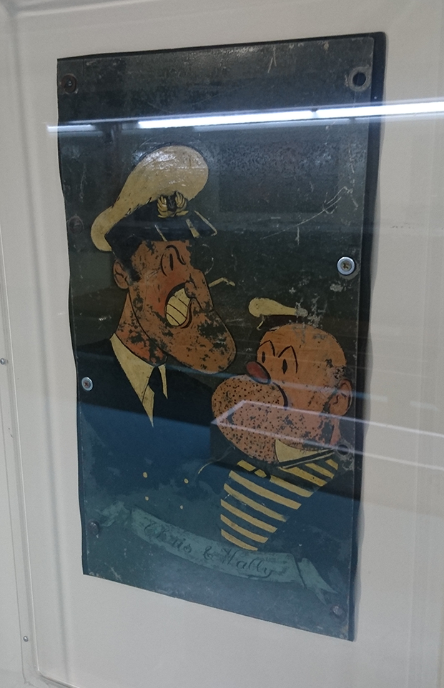
As can be seen the aircraft has been heavily damaged, and in fact the box art for Special Hobby’s 1/48 scale model kit includes this damage.  What they seem to have missed though is the nose art that was on the left hand side and was removed from the aircraft before it was dumped over the side, and which is now on display in the Fleet Air Arm Museum.


2016-07-29 16.12.59

Incidentally the pilot, Temporary Acting Sub-Lieutenant (A) Christopher MacLaren RNVR was awarded the Distinguished Service Cross, quite possibly for getting the aircraft back on deck!

Too Subtle?

I’ve started making new textures for the external model using Quixel, the question is are the rivets too subtle?  In reality most of the air-frame is flush riveted so they don’t really show up until you’re quite close, but does this look realistic in P3D?  First picture is a quite bad shot of the Fleet Air Arm Museum’s F1 that I took a few years ago, note although I’m quite close only the larger fasteners really pop out.

FAAM June 10 021

This next shot is in Prepar3D, ignore the shiny spinner that still needs to be textured.

2018-8-15_20-41-52-343.png

Are the rivets visible enough?  They’re currently only on the bump map so it’s just variations in the surface showing, which I like as it’s effectively what you get in reality, but is that enough for the sim?  Any thoughts in the comments appreciated.

Incidentally I have no idea what the lumps in front of the Museum’s Firefly’s windscreen are, they don’t seem to feature on in service aircraft!

Final Cockpit Textures?

Lots of tweaking the various textures and finding references for bits of text around the cockpit and I think it’s pretty much done.  There may need to be a quick re-render for the F1 cockpit as it was laid out a bit differently but that’s it.

2018-8-5_18-7-34-141

The red on the radar screen needs to be changed to black to act as a mask for the land you wouldn’t be able to see due to the Earth’s curvature, once the maths is spot on.  The only other bit of coding is to add the electrical circuit for some of the gauges as something seemed to change with P3D 4 that stopped them working.

2018-8-5_18-11-7-945.jpg

Coming in to land at St Barts using FlyTampa’s scenery for the area, definitely worth picking up if you fancy a challenge.  You should be able to make out a bit more detail on the main panel, and the gauges that aren’t currently working!

You can also make out the fixed and gyro reticles on the gyro gun sight, to see how they work here’s a WW2 instructional movie.

The Back Burner

Once the Firefly is finally done next up is the Seafire.  The Seafire lineage is a bit confusing but essentially the Seafire I was a Spitfire Vb with a hook.  Learning from this the Seafire II was a Spitfire Vc with a hook and fuselage strengthening so it could survive more than a couple of deck landings.  The Seafire III was a Seafire II with folding wings and some bits from the Spitfire IX, such as the larger elevator horns and air intake.  For the sake of my sanity I’m only modelling the II and III as the earlier windscreen with the external armour is harder to model if you haven’t got plans with the dimensions on!

Render 20170529

Cockpit Textures

After some fiddling with the settings I think I’ve got some better results with the VC textures.  They’re probably slightly more worn than you’d get in an actual service aircraft but due to the general darkness caused by the mostly black on colour scheme I think it looks better.

2018-7-31_22-17-27-534

Here you can see there’s a bit more definition to the areas of black!  I’ve also added more of the text labels the cockpit was liberally strewn with.

2018-7-30_21-58-48-576

View looking forward, you can actually make out where the fuel cock is now, directly below the artificial horizon.  For some reason the middle top position of the instrument panel never seems to have been filled with anything, despite the obvious lack of a VSI!

Finally below on the left is Specification 8/39 which was the original call for designs of a two seat, single engine, front gun fighter for the FAA, and on the right is Appendix B to Specification 5/40 which was the amended specification the Firefly was ultimately built to.  These are both in a file on the Firefly at the National Archives in Kew, which is an amazing facility if you’re looking to do some historical research.